Why experienced analysts are currently needed for FEA
Introduction
One area in engineering analysis that lacks procedures, workflows, methods, and checklists is finite element analysis (FEA). Unlike a test campaign where everything is very well documented, FEA models are usually based on the experience and choices of the analyst. This presents a contradictory situation because FEA models are often created to represent a test or to replace one altogether.
FEA is a popular technique for analyzing complex engineering structures, with applications in industries such as automotive, aerospace, medical, machinery, tools, electronics, defense, and more [1]–[5]. The application and level of detail of FEA within each of these industries varies greatly, and thus each of these industries has its own “FEA expert” with considerable experience [6] and domain expertise.
FEA demands considerable user experience because the physical problems it solves and the codes available are complex [6]. In a study involving air blast loading of a silo door, four different users of the DYNA code worked independently and produced four distinctly different results [6]. The study doesn’t imply that the users lacked experience, but it highlights the need for experience based on specific applications. In the real world, the user must make tradeoffs (also highly based on experience/ expertise) to produce reasonable results within the limits of time and cost.
With the pace at which technology and computing power are growing, FEA provides an excellent opportunity to further minimize testing and development costs as it becomes easier and easier to solve complex problems. However, if the results of the FEA rely heavily on user experience, which can take significant time to develop (over ten years in the authors opinion), this benefit of FEA can appear farfetched. Especially for new companies incorporating these techniques. So why does FEA require experienced analysts, and what are the critical concerns in developing the FEA model?
Mesh Sensitivity
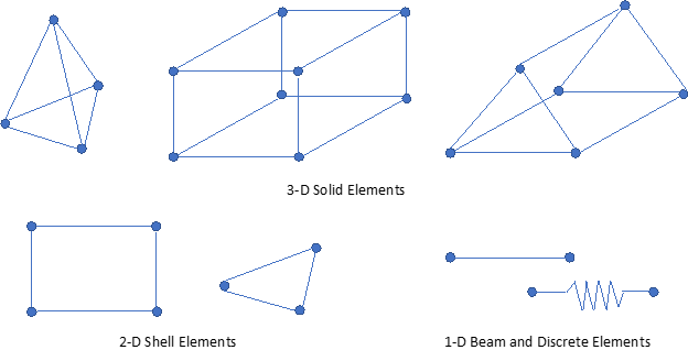
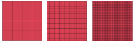
Structures being analyzed using FEA are first discretized into elements. This process is known as meshing. A suitable element size must be selected for meshing as the accuracy and the computational time depend on it. Generally smaller mesh sizes increase accuracy but also require higher computational power.
Defining the optimum mesh size involves some trial and error, which may take a few minutes to several hours or even days. With experience, the user often develops a “feel” for the optimum mesh size required for specific applications. During meshing, the user must also select the appropriate element formulation. Elements are defined by a collection of nodes (single coordinate points) and they can be 1D, 2D or 3D with varying aspect ratios and shapes.
Meshing decisions are often the result of tradeoffs between processing time, computational cost, model simplifications, desired accuracy and the physics of the problem. FEA analysts are responsible for selecting mesh parameters for the best solution and experience enables the analyst to accomplish this in the shortest time.
Material Modeling
Currently, there are over 160,000 engineering materials [8], and most applications require knowledge of a variety of materials. For example, an aircraft is constructed using metals, composites, plastics, polymers, and more, which have a high degree of variance in properties. The FEA analyst is responsible for selecting material models that capture the expected response of a component under the tested conditions. Many material models are available in today’s commercial FEA software. A few of these models are [7]: (note: this is not an exhaustive list by any means)
- Elasticity models
- Represent material behavior in the elastic region
- Various models available for linear elasticity, orthotropic elasticity, hysteresis, Mullins effect, viscoelasticity etc.
- Can be combined with Equation of State
- Plasticity models
- Represent material plasticity
- Can be rate-dependent or rate-independent plasticity
- Various models available to represent hardening, creep, strain-rate sensitivity, flow-stress, heat generation by plastic work, porous plasticity, etc.
- Can be combined with Equation of State
- Models also available for crushable foams, concrete, polymers, composites etc.
- Models for other behaviors
- Damage modeling
- Electrical behaviors such as conductivity, piezoelectricity
- Thermal
- Fluid flow, etc.
After selecting the appropriate model, the analyst must also determine the right material constants. Coupon and component level testing may be required for determining some of these constants if the data is not readily available.
Selecting an appropriate material model and gathering the required material constants can be a daunting task. A lot of time and effort goes into this part of the FEA model, especially for complex cases. It is easy to understand the need for an experienced analyst in your team.
Boundary Conditions, Loads and Contact Surfaces
Setting realistic boundary conditions and loading requires a sound understanding of the constraints in a given structure and the applied external loads. Boundary conditions should always be close to the actual operating/ tested condition. In some instances, simplifications and approximations are required due to limitations in modeling. Oversimplifying boundary conditions is a common source of errors in FEA, leading to incorrect models and answers [10].
Contact surfaces occur when two or more bodies begin to intersect. It is common in mechanical systems such as metal formation, vehicle crash, projectile penetration, various seal designs, and bushing and gear systems[11]. In such instances, it is necessary to model contact between different components. For example, a rectangular blank is formed into the required shape through contact with a punch and die during sheet-metal formation. In this case, contact locations are between the blank, punch and die.
Nowadays, most FEA software offer automatic contact formulations which is ideal for simple cases and contact; however, the analyst needs to use their expertise to ensure proper function for problems such as high velocity impacts or contacts between fluids and solids. In cases involving sliding contacts, the analyst also needs to define the correct coefficient of friction between bodies, which can become challenging. The analyst should also monitor contact forces to ensure the results are feasible, especially for contact between bodies with a big difference in stiffness. In addition, contact definitions also allow several user-defined parameters that can lead to errors if misapplied.
Processing
After setting up the problem parameters, the analyst must select the method of processing the input with the selected code. Some FEA codes provide several methods of processing the input. For smaller domain problems, a personal CPU or a single node on a cluster may be sufficient. For larger domain problems parallel computing can be a good solution, however, it has its own nuances.
In the authors’ personal experience, there have been several instances where the same problem produces different results when the number of cores for parallel processing is changed. The cores influence the decomposition of a problem which can also be controlled. Altering the decomposition of the model for the same number of processing cores can also result in differences in results. In addition, the version of code used for solving the problem can also sometimes produce differing results. It is always advisable to use the same code version and processing settings for an entire project.
Post Processing

Conclusions
It is evident from this discussion that FEA requires user experience to define the problem correctly for obtaining results within finite time and costs. The analyst must also understand the physical problem being analyzed. While it is not easy to accelerate the time it takes to gather engineering skills, what are some solutions to accelerate the FEA process?
Over time, an analyst develops expertise in FEA of specific problems. If a company doesn’t invest in documenting the best practices and procedures for their application, this knowledge is often lost when the analyst leaves. The authors recommend incorporating the following practices for reaping the most benefit out of a robust engineering process like FEA.
- Create a working checklist and update it frequently with new lessons learned
- Create a working document for procedures and practices. Every analyst in the team should be able to access this document to have a good starting point. For example, documenting the process of extracting data from coupon level tests and generating appropriate material constants for a selected material model
- Invest in creating databases of validated models, materials, and procedures. Often, analysts create simple models to understand a process or validate a method or material model. A database should be created where all these models are well documented and accessible to all analysts for decision making. A database of validated materials should also be created and, if possible, encrypted so that a standard set of material models are used for all problems.
FEA is booming, and although user experience is a crucial ingredient in creating good models, the authors believe that technology will soon overcome this shortcoming. The key to achieving this is making comprehensive databases of both good and bad models and creating processes, methods, workflows, and checklists.
The authors invite all FEA users to fill out the following survey to gather data for future articles and inform FEA engineers across the globe. The authors also invite all FEA users to share their experience on the topic and begin discussions in the comments section below.
References
[1] P. Giangrande, V. Madonna, G. Sala, A. Kladas, C. Gerada, and M. Galea, “Design and testing of PMSM for aerospace EMA applications,” 2018. doi: 10.1109/IECON.2018.8591318.
[2] P. V. Pinchuk, S. V. Leonov, and I. A. Levandrovskaya, “Experience in using finite element analysis for predicting and diagnosing spleen injuries,” Военно-медицинский журнал, vol. 342, no. 7, 2021, doi: 10.52424/00269050_2021_342_7_11.
[3] K. I. Jang et al., “Self-assembled three dimensional network designs for soft electronics,” Nature Communications, vol. 8, 2017, doi: 10.1038/ncomms15894.
[4] P. M. Kurowski, “TEACHING FINITE ELEMENT ANALYSIS FOR DESIGN ENGINEERS,” Proceedings of the Canadian Engineering Education Association (CEEA), 2011, doi: 10.24908/pceea.v0i0.3839.
[5] V. R. Deulgaonkar, “Finite element analysis and experimental simulation of chassis mounted platform for off-road wheeled combat and transport utility vehicles,” International Journal of Vehicle Structures and Systems, vol. 10, no. 1, 2018, doi: 10.4273/ijvss.10.1.14.
[6] J. A. Zukas and D. R. Scheffler, “Practical aspects of numerical simulations of dynamic events: Effects of meshing,” International Journal of Impact Engineering, vol. 24, no. 9, 2000, doi: 10.1016/S0734-743X(00)00012-9
[7] Manual, A.U., 2020. Abaqus User manual. Abacus.
[8] M. F. Ashby, “Materials Selection in Mechanical Design Third Edition,” Design, 2005.
[9] M. K. Thompson and J. M. Thompson, “Defining Material Properties,” in ANSYS Mechanical APDL for Finite Element Analysis, 2017. doi: 10.1016/b978-0-12-812981-4.00005-8.
[10] R. Marinescu, D. J. Daegling, and A. J. Rapoff, “Finite-element modeling of the anthropoid mandible: The effects of altered boundary conditions,” in Anatomical Record – Part A Discoveries in Molecular, Cellular, and Evolutionary Biology, 2005, vol. 283, no. 2. doi: 10.1002/ar.a.20166.
[11] N. H. Kim, Introduction to nonlinear finite element analysis. 2015. doi: 10.1007/978-1-4419-1746-1.
A fascinating discussion is definitely worth comment. I think that you ought to write more on this issue, it may not be a taboo matter but typically people dont discuss these topics. To the next! All the best!!
Thank you for your kind words! Keep coming back for more content 🙂
Very nice post. I definitely appreciate this site. Stick with it!